Windows Portable Executable (PE) Files Structure
Written by Anonymous on Oct 05, 2021You can always read the latest version of the post at https://filovirid.com
The structure (format) of the Windows Portable Executable (PE) files is not that difficult, but the problem is that I couldn't find a nice, complete tutorial about it. So I decided to write my own version explaining everything completely from scratch. So this will be a very long, long post!
If you think something is wrong in this post, or if you have any suggestion, please feel free to write your comment. Here is the table of content:
Table of Contents
Requirements
You don't need to know a lot about windows internals or different tools to understand this tutorial, but I think it would be helpful if you know a little bit about processes and memory management in operating systems.
Before starting the tutorial, you need to download and install Explorer suite, which is a PE file editor/viewer and it's free. You also need to download x64dbg. There is no need to install it just extract it somewhere so that you can use it (we are going to use x32dbg which is the 32-bit version of x64dbg but they are both in the same package).
I already compiled a sample executable file which does nothing but showing a message and exit. You can download it from here. The zip file is password-protected and the password is: password
Some important definitions:
We are going to use some specific terms which we need to know their definition before exploring PE files. So here is the definition of some of these keywords.
- PE32: 32-bit portable executable
- PE32+: 64-bit portable executable
- WORD: two bytes of data (also known as DW)
- DWORD: four bytes of data (also known as DD)
- BYTES: one byte of data (also known as DB)
- Section: a basic unit of code in a PE file is called a section. There are different possible sections in a PE file each has its own purpose:
- Executable Code Section (commonly named .text or .code section)
- Data Sections (of which .data, .rdata, .bss are types)
- Resources Section (commonly named .rsrc for storing resources of the PE file like icons, images, dialogs, etc)
- Export Data Section (commonly named .edata specially for .dll files when you are developing a library so that other codes can use it.)
- Import Data Section (commonly named .idata). All the functions that you are using in your code from third-party libraries like kernel32.dll or user32.dll
- Debug Information Section (commonly named .debug). For debugging purpose!
- Object file: The output of the assembler is called object file (you can also think of it as the input of the linker).
- Image file: The output of the linker is called image file. Now this image file can be an executable file (.exe) or a library file (.dll).
- Binary file: The binary file is either an object file or an image file.
- Windows loader (or just loader): The program which is responsible to load a PE file into the memory. When a PE file is loaded in the memory, the in-memory version is called module.
Process and virtual memory management
(if you already know a little bit about process and memory management, then you can skip this section)
The definition of a process is different from an executable file. An executable file is the output of the compiler (and linker). An executable file contains different sections and headers (parts which give information about sections and the structure of the .exe file). When you try to execute the file, the operating system tries to open and read some information from the file and load it into the memory. A process is an active execution of the executable file in memory and CPU. A process can have several states (active, suspended, dead).
You never work directly with the physical memory, but instead, with something called virtual memory. As the name suggests, it's just a virtual thing and doesn't exist. So here is how it works: Physical memory is limited (4GB, 16 GB,...) but the OS is able to execute lots of executable files at the same time. This can be done with the help of virtual memory. When you execute a binary file, the OS will create an imaginary space for your binary (for 32-bit OS, this space is 4GB which might be bigger than the actual amount of RAM you have!). This space is exclusively for one process. Every process has its own 4GB virtual space. Each 4GB space is divided into some smaller parts called page (which is usually 4KB). In reality, one process, at the time of execution, may only need two pages (8KB) not the whole 4GB. Therefore, the OS only needs to keep track of those useful pages and keep them in the memory. There is something called page table which maps these virtual addresses to physical addresses. When a page is not used by the process, the OS can save it on the disk in order to save some physical memory. This procedure is called swapping.
The 4GB memory (in 32-bit machines) dedicated to each process is called Virtual Address (VA) Space. When you use linkers (let's say Microsoft linker), the linker specifies the start address of the Virtual Address space that should be allocated by the OS. This default address can be found in the header of the .exe file (we will see later) and is called 'ImageBase'. There is no guarantee that the loader allocates the exact same address and because of that, all the addresses in the binary file is relative to the ImageBase and not absolute based on the ImageBase. These relative addresses are called Relative Virtual Address (RVA). Most of the addresses you find in binary files are relative. Therefore, it's important to know how to convert RVA to VA and vice versa:
VA = ImageBase + RVA
RVA = VA - ImageBase
That's it!
Another important thing is how to convert VA and RVA to file offset and vice versa. This one, we explore when we know more about PE sections.
Sample file to download
(If you are fine with downloading the sample file, you don't need to go through the compilation and linking stuff and you can skip this step)
When you donwload the sample zip file and you extract it, you will get a .exe file which is exactly 3,072 bytes and here is the source code of the file (if you don't like to download a binary file, you can compile the following code)
section .data
    szcaption db "This is caption",10,0
    sztext    db "This is the main text", 10, 0
section .text
global _main
extern _ExitProcess@4
extern _MessageBoxA@16
_main:
xor eax, eax
push eax
push dword szcaption
push dword sztext
push dword 0
call _MessageBoxA@16
push dword 0
call _ExitProcess@4
The code has been written in NASM (Netwide Assembler) and you can compile it with the following command line (assuming you save the code in miniexe.nasm file):
nasm.exe -f win32 -o miniexe.o miniexe.nasm
and then using Microsoft Visual Studio 2019 x86 linker:
link.exe miniexe.o kernel32.lib user32.lib /OUT:miniexe.exe /entry:main /subsystem:windows /nodefaultlib
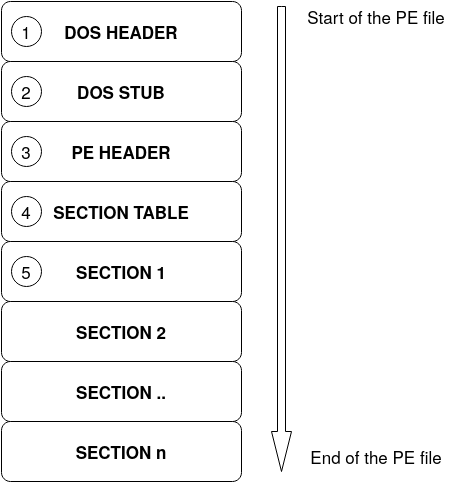
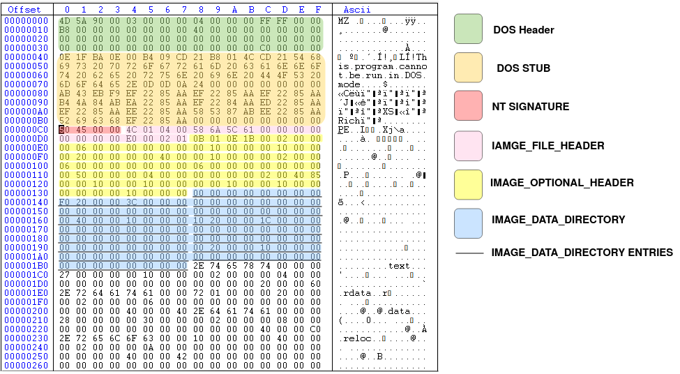
General structure of a PE file
Generally, the structure of a PE file is like the image below. There are lots of other details related to a PE file but for now it's enough to know that this is the overall structure.
DOS header
The first 64 bytes of a PE32 file is called DOS header. The structure of this header is as below
struct _IMAGE_DOS_HEADER {
    WORD   e_magic;         // Magic number 'MZ'
    WORD   e_cblp;          // Bytes on last page of file
    WORD   e_cp;            // Pages in file
    WORD   e_crlc;          // Relocations
    WORD   e_cparhdr;       // Size of header in paragraphs
    WORD   e_minalloc;      // Minimum extra paragraphs needed
    WORD   e_maxalloc;      // Maximum extra paragraphs needed
    WORD   e_ss;            // Initial (relative) SS value
    WORD   e_sp;            // Initial SP value
    WORD   e_csum;          // Checksum
    WORD   e_ip;            // Initial IP value
    WORD   e_cs;            // Initial (relative) CS value
    WORD   e_lfarlc;        // File address of relocation table
    WORD   e_ovno;          // Overlay number
    WORD   e_res[4];        // Reserved words
    WORD   e_oemid;         // OEM identifier (for e_oeminfo)
    WORD   e_oeminfo;       // OEM information; e_oemid specific
    WORD   e_res2[10];      // Reserved words
    DWORD  e_lfanew;        // File address of new exe header
  }
Since we are talking about Windows PE32 files, most of these fields are useless since this is the header for MS-DOS executable files. The reason that this header exists is just for backward compatibility between MS-DOS and Windows. So if you want to execute a Windows PE file in MS-DOS environment, you won't get an ugly error, but instead the MS-DOS operating system will read this header and execute the second part of the .exe file which is called DOS stub (look at the above figure) and all this 'DOS stub' part does is to print a nice message and tell the user that this program cannot be run in MS-DOS mode!
However, there are two important fields in the DOS header that we are interested in: i) e_magic and, ii) e_lfanew.
- e_magic is two bytes (remember it's a WORD) and it always must be 'MZ' characters (0x4D, 0x5A) after Mark Zbikowski the designer of MS-DOS executable file format.
- The other important field is e_lfanew which is four bytes (DWORD) and contains the file address of the Windows PE header.
Now let's see the DOS header of our sample miniexe.exe file. Image below is the screenshot of the CFF explorer tool as part of explorer suit program that you installed:
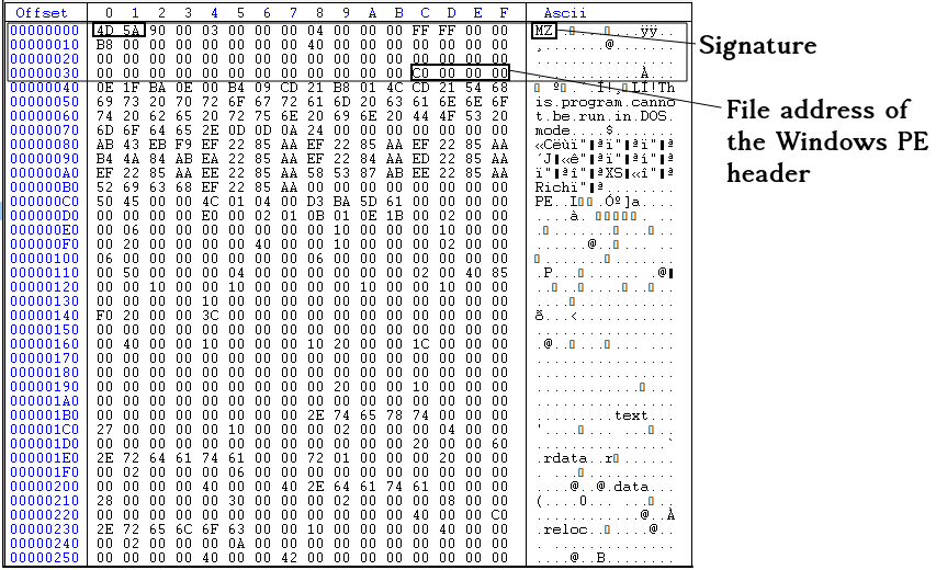
In the above image, you see the address of the PE header as 0xC0000000, but this is stored in the reverse order so the real value is 0x000000C0.
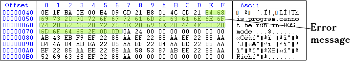
DOS STUB
Now let's take a look at the DOS stub. Whatever between the end of the DOS header (after 64th bytes from the start of the PE fie) and before the PE header (0x000000C0) is called DOS header. This is actually a piece of executable code which can be executed in the MS-DOS environment and as we said it just print an error message in STDOUT (standard output) and exit. below, you can see the hex representation of the DOS stub section.
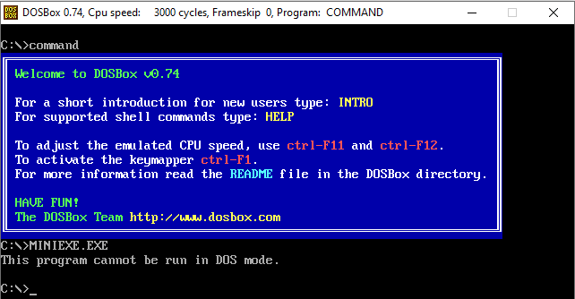
If you want to see the result of executing the DOS stub part (If you don't believe me!), you need to have MS-DOS or you can install DOSBox and execute miniexe.exe file in it. The image below shows the result of executing miniexe.exe (32-bit exe file) in DOSBox!
And if you want to see the source code of the DOS stub, you can decompile it in 16-bit mode using CFF explorer (or any other disassembler you have)
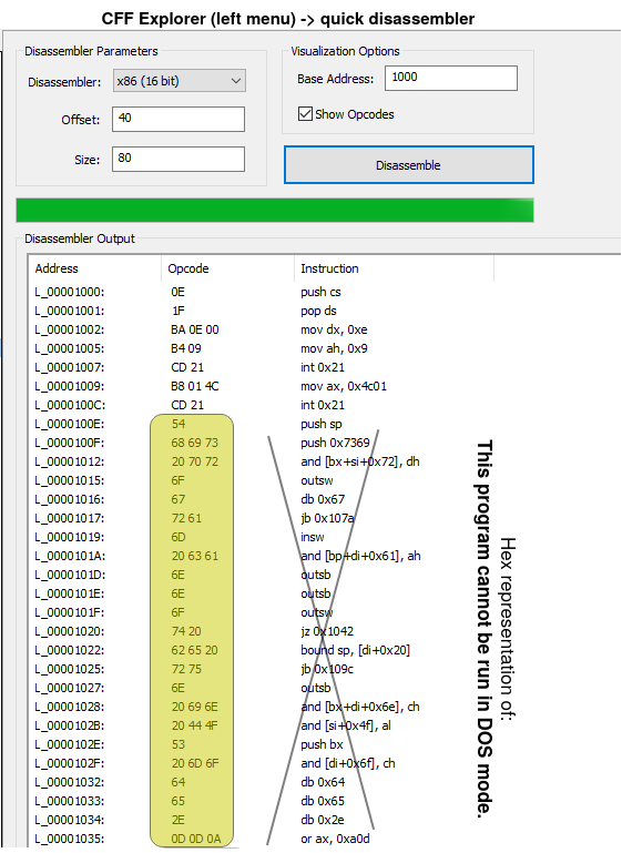
This page can help you understand the interrupts in MS-DOS. The above code just prints a message and exit. So when we are running our binary file in Windows environment, the DOS stub never get executed. In fact, we don't need DOS stub at all. It's just there for backward compatibility. Therefore, if you want to re-write some parts of your binary file, you can use the DOS stub space and some parts of the DOS header as well.
PE header
After the DOS header and DOS stub, we have PE header, which is the first important header of the file and gives us lots of information. In our sample binary, it starts from 0x000000C0. The structure of the Windows PE header (also called NT header) is as follows:
IMAGE_NT_HEADERS {
                  DWORD                             Signature;
                  IMAGE_FILE_HEADER                 FileHeader;
                  IMAGE_OPTIONAL_HEADER32           OptionalHeader;
}
The structure has one DWORD (4 bytes) which is called the signature of the PE header and two other structure as follows:
IMAGE_FILE_HEADER {
  WORD  Machine;
  WORD  NumberOfSections;
  DWORD TimeDateStamp;
  DWORD PointerToSymbolTable;
  DWORD NumberOfSymbols;
  WORD  SizeOfOptionalHeader;
  WORD  Characteristics;
}
IMAGE_OPTIONAL_HEADER {
WORD Magic;
BYTE MajorLinkerVersion;
BYTE MinorLinkerVersion;
DWORD SizeOfCode;
DWORD SizeOfInitializedData;
DWORD SizeOfUninitializedData;
DWORD AddressOfEntryPoint;
DWORD BaseOfCode;
DWORD BaseOfData;
DWORD ImageBase;
DWORD SectionAlignment;
DWORD FileAlignment;
WORD MajorOperatingSystemVersion;
WORD MinorOperatingSystemVersion;
WORD MajorImageVersion;
WORD MinorImageVersion;
WORD MajorSubsystemVersion;
WORD MinorSubsystemVersion;
DWORD Win32VersionValue;
DWORD SizeOfImage;
DWORD SizeOfHeaders;
DWORD CheckSum;
WORD Subsystem;
WORD DllCharacteristics;
DWORD SizeOfStackReserve;
DWORD SizeOfStackCommit;
DWORD SizeOfHeapReserve;
DWORD SizeOfHeapCommit;
DWORD LoaderFlags;
DWORD NumberOfRvaAndSizes;
IMAGE_DATA_DIRECTORY DataDirectory[IMAGE_NUMBEROF_DIRECTORY_ENTRIES];
}IMAGE_DATA_DIRECTORY {
DWORD VirtualAddress;
DWORD Size;
}So we are going to explain each field of all four structures defined above. You can also check Microsoft documentation about to better understand each field.
The first DWORD of the IMAGE_NT_HEADERS is called signature, and it always must be 'PE\0\0' (0x50, 0x45, 0x00, 0x00). If you change this signature, you can not execute the binary file. The second member of the IMAGE_NT_HEADERS is another structure called IMAGE_FILE_HEADER with the following fields:
- Machine: The architecture type of the computer. It can be x86, x64, etc. In CFF explorer, click on the field to see the possible options (image below):
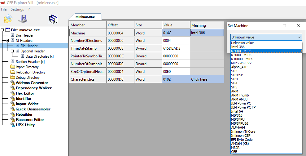
- NumberOfSections: Number of sections in the PE file. Looking at the first image of this tutorial (overall structure of a PE file), you will see that there are different sections in a PE file like .code section or .idata section( at the beginning of this tutorial I explained different sections in PE files and their definitions). This is an important field since it tells you how many sections you have, and you should read into the memory.
- TimeDateStamp: The compile time of the PE file. For example, in our case the value is 0x615DBAD3 which is '2021-10-06 17:03:47 (Wed)'. You can not count on this value since it can be changed. It's just there as extra information.
- PointerToSymbolTable & NumberOfSymbols: I don't know exactly the purpose of these values in a .exe file. I guess it's related to COFF files, not PE images (let me know if I am wrong!).
- SizeOfOptionalHeader: This is the size of the IMAGE_OPTIONAL_HEADER structure (the third member of IMAGE_NT_HEADER). Usually the size of this structure is 224 bytes (0xE0) but sometimes it can be less than that. This is a mistake people usually do to think the size is always fixed since it's not and that's why you have this SizeOfOptionalHeader in IMAGE_FILE_HEADER structure.
- Characteristics: This is also another important field. Different properties can be combined (using OR operation) to make this field. You can see the list of all possible values here. For example, in our binary file, two properties are enabled: i) IMAGE_FILE_EXECUTABLE_IMAGE and, ii) IMAGE_FILE_32BIT_MACHINE
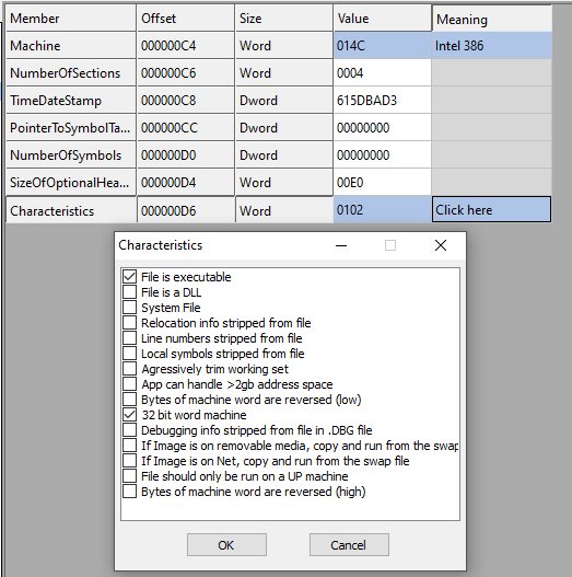
Figure 7 - miniexe.exe Characteristics
The second structure of the IMAGE_FILE_HEADRE is called IMAGE_OPTIONAL_HEADER, probably the most important part of the header in PE files. The structure consists of 9 WORDS + 2 BYTES + 19 DWORDS + IMAGE_DATA_DIRECTORY structure (which can have different length for different binaries, but most of the time its length is 128 BYTES). The following fields are in IMAGE_OPTIONAL_HEADER structure:
- magic: This magic number specifies the state of the image file. It can be one of the followings:
-
- IMAGE_NT_OPTIONAL_HDR32_MAGIC (0x10B): This is a 32-bit application.
- IMAGE_NT_OPTIONAL_HDR64_MAGIC (0x20B): This is a 64-bit application.
- IMAGE_ROM_OPTIONAL_HDR_MAGIC (0x107): This is a ROM image.
-
- MajorLinkerVersion & MinorLinkerVersion: These are the major and minor version of the linker used in the linking process. In our sample binary file, the MajorLinkerVersion is 0x0E (14) and the MinorLinkerVersion is 0x1B (27). The reason is that I linked the sample file using "Microsoft (R) Incremental Linker Version 14.27.29111.0"!
- SizeOfCode: the size of all the code section you have in your .exe file.
- SizeOfInitializedData: The size of all initialized section you have in your PE file.
- SizeOfUninitializedData: The size of all uninitialized section you have in your PE file.
- AddressOfEntryPoint: This field is a very important. The address to the first instruction which will be executed. This is the start function of your executable file and this address is a relative virtual address (RVA).
- BaseOfCode: A pointer to the beginning of the code section, relative to the image base.
- BaseOfData: A pointer to the beginning of the data section, relative to the image base.
- ImageBase: This is the preferred loading address of the PE file in the memory. This is the value that the OS will try to allocate to load the PE file in this address, but there is no guarantee to get the same value. I guess by introducing ASLR , there is no guarantee that the loaded address is the same as the ImageBase specified in the .exe file. Therefore, some relocations may be needed after loading the binary in the memory. In our sample binary, the value of ImageBase is 0x00400000.
- SectionAlignment: The alignment of the sections loaded in memory in bytes. When a binary is loaded in the memory, each section of the binary file must start from an address that is multiples of this value. For example, in our sample file, the value of SectionAlignment is 0x00001000 (4096). This means that each section must start at multiples of 4096. For example, assume that ImageBase is 0x400000 and the binary is loaded at ImageBase and also let's say the binary has two sections. If the first section is at 0x401000 and the length of the first section is 100 bytes, then the second section must start at 0x402000 (because SectionAlignment is 0x1000) and 3996 bytes in the first section will be unused.
- FileAlignment: The same as SectionAlignment but for the binary file. In our sample binary, this value is 512 (0x200) bytes. This means that the file offset of each section of the binary file must start at multiples of 512.
- MajorOperatingSystemVersion: Major version of the operating system. See the list here.
- MinorOperatingSystemVersion: Minor version of the operating system (see the list here).
- Win32VersionValue: This must be always 0.
- CheckSum: This field contains the checksum of the PE file if and only if you use an appropriate linker with the right switch. For example, in our binary sample, the value is 0x00000000 because I used Microsoft Linker, but I did not specify '/RELEASE' switch. This value is usually set for legitimate files, but not for malicious binary files (see here). The algorithm is somehow similar to CRC32 but slightly different (read more about the algorithm here). You have the right value, you can also use MapFileAndCheckSumA function.
- Subsystem: The required subsystem to run the image. The full list is here.
- DllCharacteristics: Different characteristics of the image e.g., if the DLL can move during load time. Some of these fields are actually interesting:
- IMAGE_DLLCHARACTERISTICS_FORCE_INTEGRITY: This field is set if you compile your code with /INTEGRITYCHECK switch of the Microsoft linker. This field ensures the policy that the binary that is being loaded is signed prior to loading. You can read more about it here. This means that if a malware infect a legit binary file which is already signed, the Windows loader won't load the infected file since it can not verify the signature but the malware can easily unset this property to make sure there is no integrity check involved (check a similar scenario here).
- IMAGE_DLLCHARACTERISTICS_FORCE_INTEGRITY: This field is set if you compile your code with /INTEGRITYCHECK switch of the Microsoft linker. This field ensures the policy that the binary that is being loaded is signed prior to loading. You can read more about it here. This means that if a malware infect a legit binary file which is already signed, the Windows loader won't load the infected file since it can not verify the signature but the malware can easily unset this property to make sure there is no integrity check involved (check a similar scenario here).
- SizeOfStackReserve: The number of bytes to reserve for the stack. Only the memory specified by the SizeOfStackCommit member is committed at load time; the rest is made available one page at a time until this reserve size is reached (from Microsoft doc).
- SizeOfHeapReserve: The number of bytes to reserve for the local heap. Only the memory specified by the SizeOfHeapCommit member is committed at load time; the rest is made available one page at a time until this reserve size is reached (from Microsoft doc).
- SizeOfStackCommit: The number of bytes to commit for the stack (from Microsoft doc).
- SizeOfHeapCommit: The number of bytes to commit for the local heap (from Microsoft doc).
- LoaderFlags: This field is obsolete and not used anymore.
- SizeOfHeaders: This value is the sum of the sizes of all headers in the PE file rounded to the first Multiple of the value specified in FileAlignment. For example, in our binary sample, FileAlignment is 512 (0x200) and the sum of all headers is:

- SizeOfImage: The size of the image in bytes including all headers. This value must be a multiple of FileAlignment.
- NumberOfRvaAndSizes: This is the number of records (entries) in the DataDirectory array of the IMAGE_OPTIONAL_HEADER. This value is usually 0x10 (16) but it may be less than 16.
- DataDirectory: A pointer to the first entry of the IMAGE_DATA_DIRECTORY structure. First, let's explain a little bit about IMAGE_DATA_DIRECTORY structure. Each entry of the DataDirectory gives an address and size of a table or string that is used by Windows when loading a binary file into the memory. There are 16 different types of entries in DataDirectory array, each serves a special piece of information. A wrong belief is that all the entries must be always present. This is wrong! Since some entries may be missing if the binary file not use it. For example, Resource table is one of the entries (third entry) and it contains information about resources like icons and images in the PE file. Each entry of the DataDirectory is always in a specific index as follows:
Table 1 - Entries of the DataDirectory array INDEX VALUE MEANING 0 IMAGE_DIRECTORY_ENTRY_EXPORT The export table address and size 1 IMAGE_DIRECTORY_ENTRY_IMPORT The import table address and size 2 IMAGE_DIRECTORY_ENTRY_RESOURCE The resource table address and size 3 IMAGE_DIRECTORY_ENTRY_EXCEPTION Exception directory 4 IMAGE_DIRECTORY_ENTRY_SECURITY Security directory 5 IMAGE_DIRECTORY_ENTRY_BASERELOC Base relocation table 6 IMAGE_DIRECTORY_ENTRY_DEBUG Debug directory 7 IMAGE_DIRECTORY_ENTRY_ARCHITECTURE Architecture-specific data 8 IMAGE_DIRECTORY_ENTRY_GLOBALPTR The relative virtual address of global pointer 9 IMAGE_DIRECTORY_ENTRY_TLS Thread local storage directory 10 IMAGE_DIRECTORY_ENTRY_LOAD_CONFIG Load configuration directory 11 IMAGE_DIRECTORY_ENTRY_BOUND_IMPORT Bound import directory 12 IMAGE_DIRECTORY_ENTRY_IAT Import address table 13 IMAGE_DIRECTORY_ENTRY_DELAY_IMPORT Delay import table 14 IMAGE_DIRECTORY_ENTRY_COM_DESCRIPTOR The CLR runtime header address and size 15 RESERVED, MUST BE ZERO -
Although each entry of the DataDirectory has a completely different purpose, all of the entries share a very same structure defined above as IMAGE_DATA_DIRECTORY, which is eight bytes long with two fields:
-
- VirtualAddress: The relative virtual address of the of the table/data related to this entry.
- Size: The size of the table/data.
Figure 9, shows the overview of all the headers we read so far, each specified with a different color.
In the next section, we will explain about section header, the last important header of a PE file and then we will get back to DataDirectory and explain a few entries.
Section Table
Another part of the PE file, as specified in Figure 1 of this tutorial is called section table. We already explained about different types of sections in a PE file like .text, .data, .rsrc sections. Section Table contains all the necessary information about each section in the PE file. The number of rows in the Section Table shows the number of sections we have in the PE file. The Section Table immediately follows the IMAGE_OPTIONAL_HEADER structure. Therefore, it's exactly after the DataDirectory array. The structure of the Section Table is as follows:
IMAGE_SECTION_HEADER {
  BYTE  Name[IMAGE_SIZEOF_SHORT_NAME];
  union {
    DWORD PhysicalAddress;
    DWORD VirtualSize;
  } Misc;
  DWORD VirtualAddress;
  DWORD SizeOfRawData;
  DWORD PointerToRawData;
  DWORD PointerToRelocations;
  DWORD PointerToLinenumbers;
  WORD  NumberOfRelocations;
  WORD  NumberOfLinenumbers;
  DWORD Characteristics;
}
Each entry of the IMAGE_SECTION_HEADER is exactly 40 bytes. Here is the description of each field:
- Name: an array of bytes with the length of 8 (IMAGE_SIZEOF_SHORT_NAME = 8). Note that this is not necessarily a null-terminated string, but null-padded string. So if the section name is exactly 8 characters, then there will be no null character. If the length of the section is 5 characters, then there will be 3 null character to fill the Name field. The Name of the section is not important at all. The loader does not care about the name, and it's just there as a hint. You can change the name to whatever you want and still the binary file can be executed perfectly!
- PhysicalAddress/VirtualSize: This is the total size of the section when it is loaded into the memory in bytes.
- VirtualAddress: The address of the first byte of the section when loaded into the memory. This is a relative virtual address (RVA) (relative to the base address).
- SizeOfRawData: The size of the initialized data on disk, in bytes. This value is the multiple of FileAlignment value of the IMAGE_OPTIONAL_HEADER. We'll see an example later.
- PointerToRawData: a pointer to the first byte of the section's data in the PE file. Basically, this is the file offset of the beginning of the section on disk.
- PointerToRelocations: The file pointer to the beginning of relocation entries for the section. This is zero for executable images.
- PointerToLinenumbers: Apparently, this value should be zero for an image since COFF debugging information is deprecated.
- NumberOfRelocations: This value is also zero for executable images.
- NumberOfLinenumbers: This value is also deprecated and should be zero.
- Characteristics: This field describes the characteristics of each section. There are different possible values for this field which can be combined together with or operation. For example, it shows if the section contains executable code or not, the section can be executed, read or written and etc. For the full list of all possible values see here.
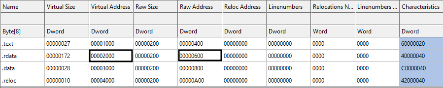
Now let's check some of the sections of our sample binary file to get more familiar with the concept. Figure 10, shows the structure of the first section in our sample binary file. As we mentioned, there are four sections in our sample file: i) .text section, ii) .rdata section, iii) .data section and finally, iv) .reloc section.
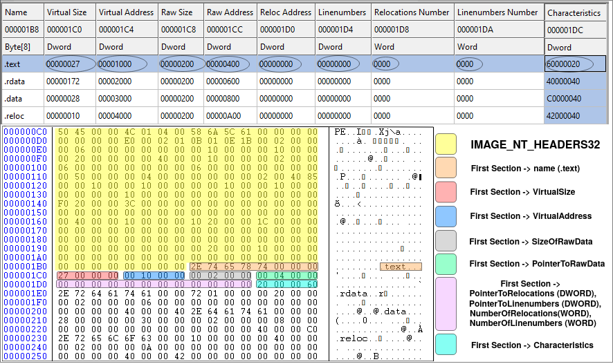
Now let's check the first section of our sample file. It begins right after the IMAGE_OPTIONAL_HEADER. Each record is 40 bytes long and in Figure 10, the first record is highlighted. It begins with 0x2E (.), 0x74 (t), 0x65 (e), 0x78 (x), 0x74 (t) followed by three zeros to fill the eight bytes for the Name field. The second field is VirtualSize which is 0x00000027 (39). This means that the length of the .text section is 39 bytes! As we know, the .text section is actually the executable code of the binary file (we know it not becase the name of the section is ".text" but because of the Characteristics of the section which is marked as executable). Therefore, the executable code of our binary is only 39 bytes which is very small. This is because the binary file does nothing but print a message using MessageBoxA function and then exit. Let's check the source code in x32dbg (we already have it installed as it was part of the requirements of this tutorial).
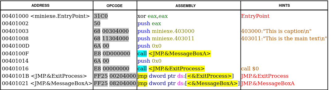
The OPCODE column (hex representation) of Figure 11, shows the operational code of the ASSEMBLY column. You can count the OP-codes and see it's exactly 39 bytes begins at the virtual address (VA) of 0x401000 since the ImageBase is 0x400000 and the VirtualAddress of the .text section (this is RVA) is 0x1000 (first row of the table in Figure 10). The SizeOfRawData for the .text section is 0x200 (512) bytes, while we know that the actual size is 0x27 (39) bytes. This is due to the fact that the SizeOfRawData must be a multiple of FileAlignment (which is 512 bytes). Therefore, anything less than 512 bytes will be rounded to 512 and filled with zeros. The same is true for memory. The .text section begins at RVA 0x1000 and the length is 0x27 bytes but the next section (.rdata) begins at RVA 0x2000 and this is because of the value specified in SectionAlignment (0x1000) meaning that any new section must start at multiple of SectionAlignment.
DataDirectory Entries
Now that we know a little bit about PE files, it's time to explore DataDirectory array (remember that DataDirectory array is the last member of IMAGE_OPTIONAL_HEADER32). As we said, DataDirectory array is an array of 16 elements, all of them have the same structure defined in IMAGE_DATA_DIRECTORY (consists of 2 DWORDS, 8 bytes in total). Each member of the DataDirectory array has a specific purpose and resides in one of the PE sections (remember that in a PE file, we have only headers and sections. So whatever that is not in headers, it's in one of the sections). As shown in Table 1, a typical DataDirectory has 16 entries. Each entry (except for the reserved one) is important and serves a purpose. Here we are going to introduce some of the important ones and explain the structures.
Import Directory and Import Section
When you are writing your code (in whatever language), sometimes you need to call/use some functions from a library or .DLL file (DLL stands for Dynamic Link Library). For example, to show a message box to the user, you need to use MessageBoxA function. It doesn't matter if you never heard of this function or never used it before. Whatever library or function you are using to show a message box is probably using this function behind the scene, since this is one of the Windows API functions. This function is part of user32.dll file in your operating system (C:\Windows\System32\user32.dll). Think of the Windows DLL files as something like .SO files in Linux. Conceptually they are the same thing but in different OSes. So let's say you use this function, you compile and link your code, and you get the executable file working perfectly fine but how the linker knows about this external function in your code? Where it can be found at run-time? Is it always in a fixed address in the memory? The answer is NO, the address may change every time you execute your file. Therefore, there must be a way to somehow know the address of MessageBoxA without knowing the address of MessageBoxA!!
This is a collaboration between the compiler (or assembler), the linker and the Windows loader. Consider the assembly code I wrote at the beginning of the tutorial. The 7th line is extern _MessageBoxA@16 and in line 14, there is a call to this external symbol: call _MessageBoxA@16. Here is the listing output of the NASM (use -l switch to create the listing file in NASM):
     1                                  section .data
     2 00000000 546869732069732063-     	szcaption db "This is caption",10,0
     2 00000009 617074696F6E0A00
     3 00000011 546869732069732074-     	sztext	db "This is the main text", 10, 0
     3 0000001A 6865206D61696E2074-
     3 00000023 6578740A00
     4
     5                                  section .text
     6
     7                                  global _main
     8
     9                                  extern _ExitProcess@4
    10                                  extern _MessageBoxA@16
    11
    12
    13                                  _main:
    14 00000000 31C0                    xor eax, eax
    15 00000002 50                      push eax
    16 00000003 68[00000000]            push dword szcaption
    17 00000008 68[11000000]            push dword sztext
    18 0000000D 6A00                    push dword 0
    19 0000000F E8(00000000)            call _MessageBoxA@16
    20 00000014 6A00                    push dword 0
    21 00000016 E8(00000000)            call _ExitProcess@4
Looking at line 19, there is a call instruction (0xE8) to _MessageBoxA@16, but this is an external symbol that the compiler (here assembler) doesn't know anything about it! So you see the address of the call is all zeros (0xE8 00000000). The same is true for line 21 and call to _ExitProcess@4. Now, this is the duty of the linker (here Microsoft linker) to correctly fix up the call instruction. Let's take a look at the output of the assembler/compiler (here we use NASM as the assembler) which is an object file to see how it works (we explained how to create the object file here). I use DUMPBIN to dump the relocation table of the object file.
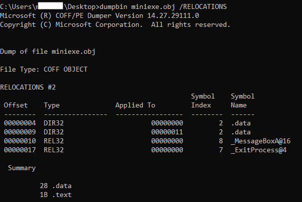
Figure 12, shows the relocation table of the object file, created by the compiler/assembler to be used by the linker. This won't be part of the final executable file, but just there to help the linker to better understand which parts of the compiled code need fixups. The first column (Offset) is the location from the beginning of the .text section. Looking at the third row, it tells the linker that: offset 0x10 (16) of the .text section is of type REL32 and the current value is 0x00000000 and must be fixed up (REL32 is 32-bit relative address). Matt Peitrek has this nice article about linkers you may want to read it as well.
So now we know that it's the responsibility of the linker to fill missing addresses in the object file using the relocation table in the object file. However, even the linker doesn't know the address of the loaded .DLL files at run-time since in every execution of the executable file, the .DLL files may load in different addresses. To solve this problem, linkers use a very clever approach. Here is what linkers do:
- Create a table (also known as jump table) in the .text section. Each row of this table is in a form of
jmp dword ptr ds:[ADDR_XX]corresponding to one function (e.g., MessageBoxA) from a shared library (e.g., user32.dll). - For every call to that specific function, the op-code will change: from
E8 (00000000)toE8 (Addr of jmp row in the table). - Step I and II will be repeated for all the external functions from the shared library which are used in the binary file.
- Create a table (aka import table) in the binary file and specify which .DLL files must be loaded into the memory and which functions will be used.
Now the question is: what is ADDR_XX? This is an address of a DWORD in the memory which contains the real address of the function (e.g., MessageBoxA) when the Windows loader loads user32.dll into the memory. Since the linker doesn't know this address at the time of linking, it's up to the loader to fill this address in the memory at the time of loading DLL files (you can check this article for more info).
Everything will be more clear when we start exploring import address table and import directory in our sample binary file.
The import section contains information about the external libraries (i.e., .DLL files) and their functions which are used in the code. The Windows loader reads the import section and loads all the necessary DLLs into the memory, then adds the correct addresses to those functions in a table called import table. You may sometimes see that some people use the term 'import directory' instead of import section, which is basically the same thing. The import directory is nothing more than an array of a specific structure called IMAGE_IMPORT_DESCRIPTOR with the following fields:
IMAGE_IMPORT_DESCRIPTOR{
    OriginalFirstThunk    DWORD;
    TimeDateStamp         DWORD;
    ForwarderChain        DWORD;
    Name                  DWORD;
    FirstThunk            DWORD;
}
In other resources, you may see the first element as 'Characteristics' not the 'OriginalFirstThunk' but the correct and new version is this one since Microsoft changed the meaning and never updated the WINNT.h header file. Let's see the role of each member:
- OriginalFirstThunk: This field is also known as Import Lookup Table. This is a DWORD value which contains the RVA to an array of DWORDs. Each member of the array is one DWORD that is called IMAGE_THUNK_DATA. The length of the OriginalFirstThunk array is equal to the number of imported functions plus one (the last member is a null DWORD to indicate the end of the array). IMAGE_THUNK_DATA (which is just one DWORD) can be interpreted in two different ways: First, we need to look at the most significant bit (MSB) of the DWORD (this is 31th bit in 32-bit applications). If MSB is set (i.e., 0x8???????), then bits 0-15 (the first 16 bits) shows the ordinal number of the function in the DLL file (in DLL files, each function exported by two unique features: i) Ordinal and, ii) name. When you want to import a function in your code, you can choose to use the ordinal number or the function name. We will read more about this part in the Export section or you can also read this). If MSB is not set (i.e., 0x0???????), then bits 0-30 (the first 31 bits) is the an RVA to another structured called IMAGE_IMPORT_BY_NAME with the following structure:
IMAGE_IMPORT_BY_NAME{ Hint WORD; Name1 ?; }- Hint: An index into the export name pointer table. This is just a hint! if it's there, then it's easier for the loader to find the function in the DLL. Otherwise, the loader will search the whole DLL file to find the appropriate function by matching the name of the function.
- Name1: A variable length ASCII string contains the name of the function to import. This is a null-terminated string and it's case-sensitive. If the length of the Name1+null character is an odd number, then another 0x00 will be added to align the next entry on an even boundary (for example, MessageBoxA is 11 characters + a null-terminated character = 12 bytes -> we don't need an extra 0x00 for alignment)
- TimeDateStamp: We will explain this field later. For now, just consider this field as zero.
- ForwarderChain: We will explain this field later. For now, just consider this field as zero.
- Name: This is the relative address of the ASCII string that contains the name of the DLL to load.
- FirstThunk: This field is also known as Import Address Table (IAT). This is the beautiful part of the dynamic loading and the climax of everything we said so far for dynamic loading. This FirstThunk field is the exact same copy of the OriginalFirstThunk field, as long as the binary is on the disk. At the time of loading the binary file into the memory, the loader will rewrite the elements of this array to point to the real address of the functions (e.g, MessageBoxA) in memory. So whenever we want to call MessageBoxA in our code, we use
jmp dword ptr ds:[FirstThunk entry of MessageBoxA]which is something that linker put it there for us and the loader just fill it with the correct value!
Each element of the import directory array is exactly 20 bytes (length of IMAGE_IMPORT_DESCRIPTOR = 20 ). Remember that the number of elements in the import directory array is the same as the number of imported DLL files. So in our sample binary, we are using two .DLL files: i) user32.dll (for MessageBoxA) and, ii) kernel32.dll (for ExitProcess). Therefore, import directory array has two effective members. However, there is no field to specify the length of the array instead, the final structure of the array is all zeros. Therefore, in our sample binary file, the image directory array has two members for two DLL files and another member filled with zeros (20 bytes of zeros) to indicate the end of the array.
Import Directory in practice
Having our sample binary file, let's say we want to check the imported DLL files and used API functions. So, the first thing we need to do is to find the address of the import section (or import directory) in our binary file. To do so, first we check the DataDirectory array (in IMAGE_OPTIONAL_HEADER) for the second entry (look at table 1 of this tutorial if you forgot) which is RVA and size of the import directory (you can see it in the image below).
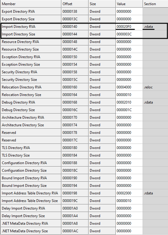
As you can see, the RVA of the import directory/section is 0x000020F0 and there is also a hint (last column of Fig. 13) which tells us that import section is part of .rdata section. However, we don't care about the names of the sections. We need to find the right section only based on address, not by the name (we already know that section's name is just a hint and anyone can change it to anything arbitrary value). Having 0x000020F0 as the relative virtual address (RVA), we check the section table (if you forgot, you can go back and read about the section table) to see this address lies in which section.
Checking the third column of Figure 14, we see that 0x000020F0 is greater than 0x00002000 and less than 0x00003000. Therefore, it belongs to the second row or let's say .rdata section (So the hint was correct!). Now it's time to find the location on the disk because 0x000020F0 is an RVA, meaning a memory address. So to convert an RVA to file offset, we use the following approach:
- Subtract the start of the section (specified in VirtualAddress field) from the RVA (here we need to subtract 0x00002000 from 0x000020F0)
- Add the 'PointerToRawData' to the result of the previous step (here we add 0x00000600 to the result of the previous step)
Therefore, we have: 0x000020F0 - 0x00002000 = 0x0F0 and then 0x00000600 + 0x0F0 = 0x6F0
This address (0x6F0) is the beginning of the import directory array on the disk as shown in Figure 15.
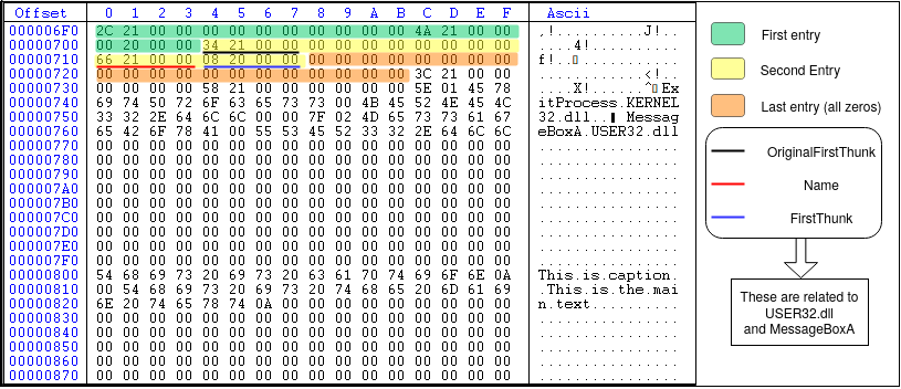
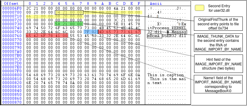
As shown in Figure 15, the import directory array has three members, two of them related to two .DLL files (user32.dll and kernel32.dll) and the last one is null to indicate the end of the array. The second entry (highlighted in yellow) is related to user32.dll and MessageBoxA function. The first four bytes of the second entry (black underline) is the OriginalFirstThunk member of the IMAGE_IMPORT_DESCRIPTOR structure. The value is 0x00002134 which is the RVA of IMAGE_THUNK_DATA array. Converting this RVA to file offset, we have 0x734 (the first element of OriginalFirstThunk array) with the value 0x00002158. Since the MSB is not set in 0x00002158, the first 31 bits of the DWORD is the RVA to IMAGE_IMPORT_BY_NAME structure. Converting the value to file offset, we have 0x758 which is the start of IMAGE_IMPORT_BY_NAME structure. The first two bytes (WORD) is the hint (0x7F, 0x02) and the rest is the null-terminated ASCII string corresponding to MessageBoxA\0 as shown in Figure 16. The second element of the OriginalFirstThunk array is NULL (DWORD starting at file offset 0x738) which means that we reached the end of the OriginalFirstThunk array (i.e., the array has only one member which is MessageBoxA. This is because we only use one function of the user32.dll).
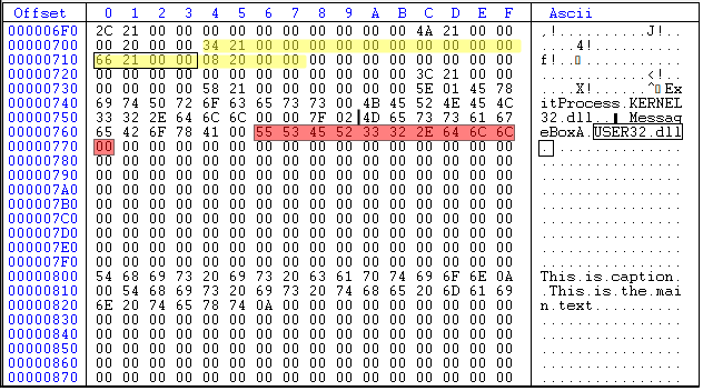
Looking again at Figure 15, the fourth DWORD of the second entry (underlined in red) is the Name field of the IMAGE_IMPORT_DESCRIPTOR which is the RVA of an ASCII string that contains the name of the DLL to load. In this example (Figure 15), the value is 0x00002166 which equals to the file offset 0x766. Figure 17 shows the highlighted value at this offset, which corresponds to the string 'USER32.dll'.
Export section
Another important entry of the DataDirectory array is called Export section. So what is export section and what it means? First, we need to know that this section is relevant to .DLL files. Dynamic Link Libraries (aka .DLLs) are modules (or libraries) in Windows operating system that contain functions and data. The functions define in a .DLL file can be used in another modules or executable files by just calling them. However, the operating system should be aware of the existence of these function before calling them. When you write a function and compile it in a .DLL file, you should define that function as Exported function and in this way the OS knows that this function is supposed to be used by another modules. Let's see an example: MessageBoxA function has been defined in user32.dll file (located in c:\windows\SysWOW64\user32.dll in 64-bit OS). If you open up the file in CFF explorer, you will see an export section on the left menu, and clicking on that shows you the list of exported functions in user32.dll. These are function that you can call from your own binary file. Look at the image below:
To practically explain this part, I am using user32.dll file on my system. You can use your own version of user32.dll, but it might be different from mine, so you won't get the same results as I show in these figures. Therefore, I uploaded my user32.dll so that you can use it. You can download it from here (the password of the zip file is 'password').
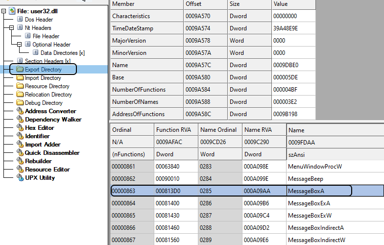
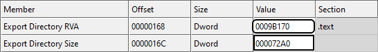
Now let's say you want to check a .DLL file (e.g., user32.dll) and you want to see the list of exported functions and get their addresses. How you can do that? Well, in .DLL files, there are two ways to export a function: i) by name and, ii) by ordinal. This means that you either specify a name for the function so that other modules can find the address of the function by the name you specified, or you specify an integer number so that other modules use this number to find the address of the function. The best way to understand it is to go step by step through an example. In order to get information about the exported functions in a .DLL file, first you need to check the .DLL file and find the address in which the information is stored. Remember that in the DataDirectory array, the first entry (index 0) is called IMAGE_DIRECTORY_ENTRY_EXPORT which contains the address and size of the export section. Looking at user32.dll file, Figure 19, the RVA of export section is 0x0009b170.
Then, we check the section table to see to which section this address belongs (Figure 20). We see that it belongs to .text section since 0x00001000 < 0x9b170 < 0x000A3000.
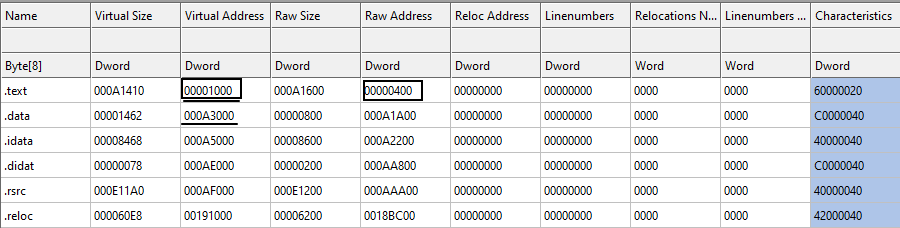
The RVA of the .text section in memory is 0x00001000 and the raw address (file offset) is 0x00000400. Our export section is at 0x9b170 (RVA). Therefore, the file offset for export section is:
0x9b170 - 0x00001000 + 0x00000400 = 0x9A570
This is (0x9A570) the start address of the export section in the .DLL file. Going to this address, you will have the following structure:
struct IMAGE_EXPORT_DIRECTORY{
    DWORD    Characteristics;
    DWORD    TimeDateStamp;
    WORD    MajorVersion;
    WORD    MinorVersion;
    DWORD    name;
    DWORD    base;
    DWORD    NumberOfFunctions;
    DWORD    NumberOfNames;
    DWORD    AddressOfFunctions;
    DWORD    AddressOfNames;
    DWORD    AddressOfNameOrdinals;
}
Now let's see the definition of each field of IMAGE_EXPORT_DIRECTORY:
- Characteristics: This field is reserved and must be zero!
- TimeDateStamp: The time and date the export data created.
- MajorVersion: The major version number
- MinorVersion: The minor version number
- name: The RVA of the ASCII string that contains the name of the .DLL file. Note that the name of the file can be changed by the user. So this is the internal name used by the system.
- base: The starting ordinal number for exports in this image. This field specifies the starting ordinal number for the export address table. While in MSDN it says that it usually starts from 1, in real cases, it may start from any number (like in our example).
- NumberOfFunctions: The number of functions that are exported by this module.
- NumberOfNames: The number of functions exported by name. Note that this value is not always the same as NumberOfFunctions since some functions may export by ordinals as we said.
- AddressOfFunctions: This is an RVA to a table (or array) called Export Address Table (EAT). We will explain this table as well.
- AddressOfNames: This is an RVA to a table (or array) called Export Name Table (ENT).
- AddressOfNameOrdinals: This is an RVA that points to a table (or array) called Export Ordinal Table (EOT).
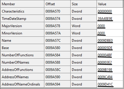
Let see the example for our user32.dll file in Figure 21. Looking at figure 21, the Characteristics field is zero as we said (reserved), the TimeDateStamp is 0x39A48E9E which is '2000-08-24 04:55:26 (Thu)', the MajorVersion and the MinorVersion are both zero. The name field is the RVA to the .DLL name with value 0x0009DBE0, convert it to file offset (0x0009DBE0 - 0x00001000 + 0x400), we have 0x9CFE0 and going to this location in the file, we have the ASCII string (0x55 0x53 0x45 0x52 0x33 0x32 0x2E 0x64 0x6C 0x6C 0x00) which is "USER32.dll\00". The base field is 0x000005DE which is the starting ordinal number for the export address table. The NumberOfFunctions in our version of user32.dll is 0x000004bF (1215 functions). The next field is the NumberOfNames which is equal to 0x3E2 (994). This value is the number of functions exported by name. So there are some functions in user32.dll that not exported by name (1215 - 994). The RVA to the export table address table is 0x9B198, the RVA to the export name table is 0x9C494 and the RVA to export ordinal table is 0x9D41C.
Now we know that there are three important tables in the export section: i) Export Address Table (EAT), ii) Export Name Table (ENT) and, iii) Export Ordinal Table (EOT). These tables are working together to make it easier for the operating system to find the address of the exported functions. We also know that one function in a .DLL file can be exported by name or ordinal. So how the OS find the RVA of a function?
There are two possible scenarios:
- The function is exported by name:
- The loader gets the AddressOfNames field of IMAGE_EXPORT_DIRECTORY structure (ENT).
- The loader gets the AddressOfNameOrdinals field of the IMAGE_EXPORT_DIRECTORY structure (EOT).
- The loader gets the AddressOfFunctions field of the IMAGE_EXPORT_DIRECTORY structure (EAT).
- The loader goes through all the names in ENT to find a match (let's say the match is in the nth element of ENT)
- The loader reads nth value of the EOT to get the ordinal number (this ordinal number is the position of the RVA for the function in EAT)
- The loader uses the ordinal number in the previous step to read the RVA of the exported function from the EAT.
// let's say we are looking for MessageBoxA function in user32.dll
// i is the row number in ENT
i = Search_ENT_for_the_function_name ("MessageBoxA");
// using i, we read the value at EOT[i] to get the row number in EAT
ordinal = EOT [i];
// Now we can get the RVA of the MessageBoxA function
RVA_of_MessageBoxA = EAT[ordinal]
Simple as that! We have the RVA for MessageBoxA function. This RVA usually points to the code or data section. However, there is one exception that we need to know (I know it's getting more complicated, but this is important. We will have some examples for all of these cases). There is a concept called Forwarder RVA which means that the RVA is not the address of the exported function but a pointer to a NULL-terminated string in the export section either in dllname.exportfunction form or dllname.#number format. So then, how do we know the RVA we found is a forwarder RVA (i.e., points to another function in another DLL file) or an export RVA (i.e., points to the actual code of the function)? Well, it's simple: if the RVA points to somewhere inside the export section i.e.,
IMAGE_DIRECTORY_ENTRY_EXPORT address < RVA_of_our_function < IMAGE_DIRECTORY_ENTRY_EXPORT address + IMAGE_DIRECTORY_ENTRY_EXPORT sizeThen we know it's a forwarder RVA. If the RVA points to somewhere outside the export section, then it's the actual address to the function (usually in .text or .data section).
- The function is exported by ordinal:
- in this case, since we have the ordinal number (let's say n), the first thing we do is to subtract the IMAGE_EXPORT_DIRECTORY->base from the ordinal number to get the actual index of the EOT (let's say n).
- the loader directly gets the nth element of the EOT (i.e., EOT[n]) to get the ordinal number.
- The loader uses the ordinal number in the previous step to read the RVA of the exported function from the EAT (this is the same as step 6 of the first scenario, exported by name).
Now let's do it practically using our user32.dll file. In our sample .DLL file, here are the Export Name Table, Export Address Table and Export Ordinal Table. We also use the term RVA2FO as the function which converts RVA to file offsets.
// to get ImageBase, you just need to check the IMAGE_OPTIONAL_HEADER
ImageBase = 0x69E00000

// We get this value from IMAGE_EXPORT_DIRECTORY structure
AddressOfNames = 0x0009C494 -> RVA2FO(0x0009C494) = 0x0009B894

// We get this value from IMAGE_EXPORT_DIRECTORY structure
// Then we calculate the file offset based on the RVA
AddressOfFunctions = 0x0009B198 -> RVA2FO(0x0009B198) = 0x0009A598

// We get this value from IMAGE_EXPORT_DIRECTORY structure
// Then we calculate the file offset based on the RVA
AddressOfNameOrdinals = 0x0009D41C -> RVA2FO(0x0009D41C) = 0x0009C81C

// We get this value from the first entry of IMAGE_DATA_DIRECTORY structure (first DWORD)
Export directory RVA = 0x0009B170

// We get this value from the first entry of IMAGE_DATA_DIRECTORY structure (second DWORD)
Export directory size = 0x000072A0

// We need this interval in order to check if an RVA is a forwarder RVA or an Exported RVA
Export section interval = [0x0009B170, 0x0009B170 +  0x000072A0] = [0x0009B170, 0x000A2410]

// Same as above but in file offset instead of RVA (we don't need it)
Export section interval in the file = [RVA2FO(0x0009B170), RVA2FO(0x0009B170) + 0x000072A0] = [0x0009A570, 0x000A1810]
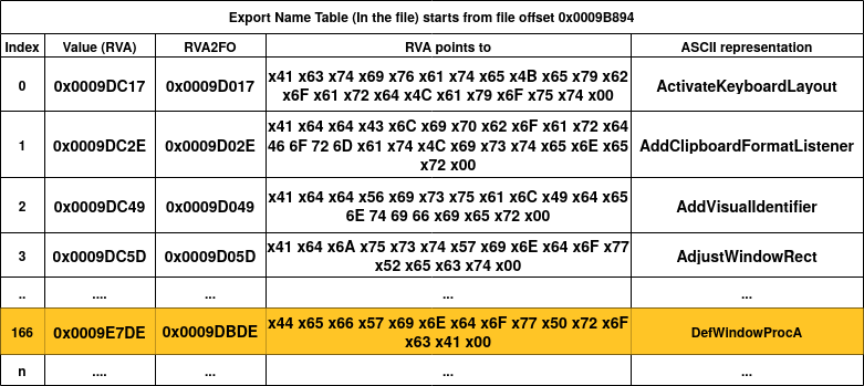
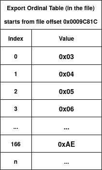
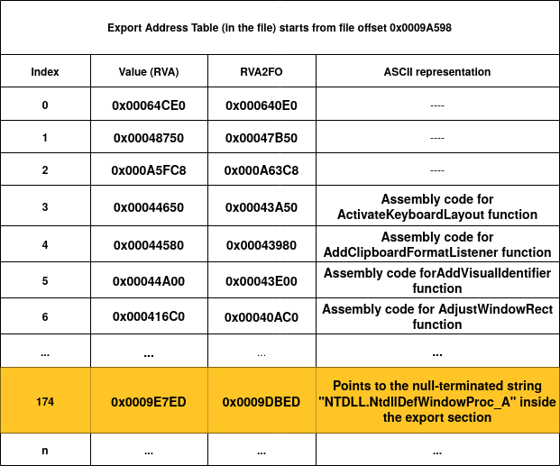
Figure 22, 23 and, 24 show the ENT, EOT and, EAT of the user32.dll file (just the first entries and one special entry highlighted in orange). Let's say the loader wants to find the RVA of the "AdjustWindowRect" function by name. The first step is to go through ENT to match the name. We can see that the forth entry of ENT has the value 0x0009DC5D and if we convert it to file offset, we get 0x0009D017 and looking at the value at this file offset, we have the matched string for "AdjustWindowRect"! Since we know that we found this match at the fourth entry of ENT (index = 3), then we get the fourth entry of EOT (EOT[3]) to get 0x06 as the ordinal number. Then, we use this ordinal number (0x06) and directly go to the seventh entry of EAT (EAT[0x06]). As you can see in figure 24, the seventh entry of EAT (with index = 6) has an RVA value of 0x000416C0 which points to the assembly code of the AdjustWindowRect function!
Now let's see an especial case that we talked about before: Forwarder RVA. In Figure 22, I've highlighted one entry, which is the 167th entry of ENT (with index 166). By checking figure 23, we know that the ordinal number of this entry is 0xAE (174). Now if we go to the 175th element of EAT (highlighted in Figure 24), we see that the value (0x0009E7ED) actually points to another null-terminated string which inside the export section interval. As you can see, the string is "NTDLL.NtdllDefWindowProc_A" which has the same format as forwarder RVAs as we explained above. This tells the loader that NTDLL should be also loaded into the memory.
So far, we covered two important members of the DataDirectory array called, import data directory and export data directory. In the next sections, we will cover other members of the DataDirectory such as relocation section, resource section and TLS section.
References
- Linkers and Dynamic Linking
- Microsoft Documentation - The .rsrc Section
- Microsoft Documentation - PE FILE RESOURCES
- Win32 Binary Resource Format
- Understanding Import Address Table
- Virus Bulletin - It's mental static!
- https://c9x.me/x86/html/file_module_x86_id_26.html
- Wikipedia - Portable Executable
- Corkami pe101
Please feel free to comment!